RESEARCH
ENGINEERING,
LLC
especially for Ionospheric Tomographic imaging Systems (ITS), a coherent receiver design.
Printer-friendly .pdf version of this page
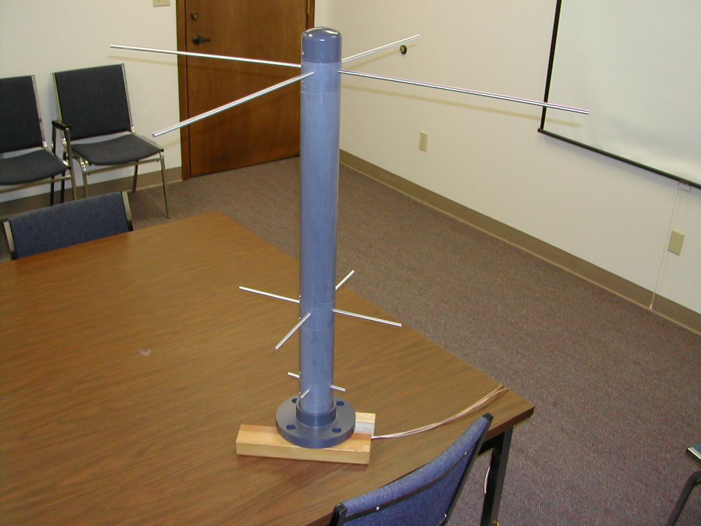
The ITS20/30 Antenna is basically a simple design of dipoles above a ground plane.
Because many of the target satellites radiate a circularly polarized signal, the ITS20/30 antenna actually uses,
at each frequency, a pair of dipoles at right angles with a common center; a 'turnstile' design.
One of the dipoles is connected in parallel with the other through a 1/4 wave delay line.
This gives 3 dB gain over a simple dipole for circularly polarized signals, and eliminates polarization
nulls from linearly polarized signals.
The dipole elements are brought together to a small circuit board that includes the delay line and an SMA connector
for attaching the antenna cable. The four antenna elements and the combiner circuit board are assembled inside a
short section of antenna mast to comprise a module that is the 'antenna' for a given frequency.
The dipole modules are stacked vertically and mounted in a single mast. Each dipole set is approximately 0.4
wavelengths over the base of the mast. With the mast positioned over a reflective ground plane, the RF 'center'
of the antenna is at the center of the base, and is the same at all frequencies.
The reflecting ground plane yields 3 dB gain over the same antenna in free space.
The antenna mast is a PVC tube that is built in sections for transport, disassembly and service.
The mast sections are overlapping in such a way so as to shed rainwater and form a rigid structure when assembled.
The design of this antenna emphasizes having an even, smooth reception pattern over the hemisphere defined by
the antenna and the ground plane. As the receiver is designed to record variations/scintillations in received signal
amplitude as well as phase, it was necessary to minimize any variations due to the receiver antenna pattern.
Thus the dipole-over-ground-plane design.
Ground Plane Notes
As noted above, a ground plane is required to achieve the designed antenna pattern.
The recommended ground plane is 3 meters x 6 meters, oriented North-South. This is the ground plane used at the
ITS10S stations in Alaska and Bellevue.
However, since the time that those installations were made, there have been other installations in Greenland and
Taiwan that have gotten good results with a 1.5 meter x 1.5 meter ground plane. By 'good results' we mean that there
is no obvious difference between the smaller size and the larger size.
We continue to specify the 3 m x 6 m size only because neither we nor (as far as we know) anyone else has done a
quantitative comparison. Such a test will be time-consuming and expensive.
It is also worth noting that the need for the kind of pattern only obtainable from the larger ground plane may not
be necessary. There are pattern anomalies caused by nearby metallic objects, regardless of ground plane size,
and the satellite beacons themselves do not have perfect patterns.
All things considered, 1.5 m x 1.5 m could be considered a minimum size, and 3 m x 6 m to be rather larger than necessary.
Why the ground plane must be supplied by the user
The reasons for making the ground plane a user supplied item are several.
Ground Plane Specifications
As noted above, the overall size of the ground plane is a matter of judgement, space availability and cost.
Whatever size is selected, the surface should be flat to 1/10 wavelength within 1 wavelength of the antenna.
If wire mesh is used, the mesh size should be no larger than 1/10 wavelength, again within 1 wavelength.
The pictures here show some actual installations.
Interaction Between the VHF (150 MHz) and L-Band (1067 MHz) Antennas
It is observed that the VHF and L-Band frequencies bear an approximate 1:9 relationship, and an effect from the
VHF antenna is expected at L-Band. Indeed, such is the case.
The complete antenna assembly (VHF, UHF and L-Band) was modeled using the antenna modeling software EZNEC.
Separate simulations were run with one of the antennas active and the other two passive.
Another set of simulations was run for each antenna alone - the other antennas were removed from the model.
VHF: There was no discernable difference between pattern of the VHF antenna with or without the presence of the UHF
and L-Band antennas.
UHF: Like the VHF results, there was no discernable difference between pattern of the UHF antenna with or without
the presence of the VHF and L-Band antennas.
L-Band: The L-Band pattern with the VHF and UHF antennas in place was a superposition of the pattern without the VHF
and UHF antennas, and three 1 dB lobes. That is, the effect of the VHF antenna was approximately +/- 1/2 dB smoothly
spread out over the reception hemisphere.
For these reasons, is seems most appropriate for the user to assess the local situation and provide the ground plane.
Assistance in the design and advice on fabrication are freely available from NWRE.
.