Printer-friendly .pdf version of this page
Background:
The classic Phase Locked Loop circuit (Gardener), including the circuit in the ITS30 series of receivers,
makes use of an integrator at its heart. This integrator will "wind-up" (the output will go to the rail)
if the input is a signal with a DC component. To deal with this, a shunt resistor is switched into the circuit
when the PLL is not locked.
If the wind-up is too fast, or the shunt resistor switching is incorrect, the lock action will be impaired.
Depending on the state of adjustment, the receiver can be rendered inoperable.
The procedure described herein minimizes the DC component presented to the PLL input, thereby minimizing the wind-up,
and adjusts the circuit that switches the shunt resistor out when lock has occurred.
This procedure is the Laboratory procedure.
The procedure described is for UHF. Adjustment for VHF and L-Band is identical
(except for the actual potentiometers adjusted.)
Note:
The frequency band at which the ITS30 will search and Lock is set by a parameter in the "receiver_param_30.dat" file.
The value in the last line of the file can be set as follows: 1 = UHF; 2 = L-Band; 3 = VHF
For later versions of the software, the parameter file is "satellite_param.dat". In this case the parameter can be set
for each satellite individually by changing the corresponding number in the "LOCK" column.
The equipment required for this procedure:
- Voltmeter - 0 - 10 Vdc; resolution +/- 1 mV
- Oscilloscope - 500 msec/div horizontal - 5 volt/div vertical
- Signal generator - 150 to 1067 MHz output at up to 0 dBm
- Test antenna - used to radiate the signal generator output to the ITS30 station antenna.
Setup:
- Remove the top cover from the receiver.
- The board you will be working with is the Detector circuit board located roughly center-rear of the receiver. It abuts the rear panel, and the external computer cable connects to it.
- Locate a row of 3 potentiometers (R1, R133, R134) located together near the centerline of the Detector, about 3/4 of the way to the rear of the board. Verify that all 3 are set to maximum (clockwise). (They will click when set to maximum, but if not, 18 turns.)
- Locate the row of 6 potentiometers positioned near the front (inner) edge of the Detector board. Looking closely, note the channel identification. The 6 channels are, from left to right: UHF Q; UHF I; VHF Q; VHF I; L-B Q; L-B I.
- Connect the voltmeter to the 2-pin Molex connector (J14) located near the right side of the board 2/3 of the way back. The voltage will typically read between 1 and 4 volts.
- Connect the oscilloscope to test point DET located near the centerline of the board, behind R1, R133, and R134.
- Position the test antenna about 10 - 20 m away from the station antenna. Connect it to the output of the signal generator.
Initial test (to verify the test setup):
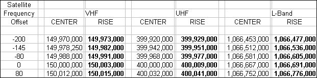
- See the attached spreadsheet for the appropriate frequencies.
- In "receiver_param_30.dat" or "satellite_paran.dat",set the Lock parameter to 1 (UHF)
- Note the frequency offset of the satellite that the receiver is waiting for. Note the time until the next satellite. Make sure no satellites will be visible for the duration of this procedure.
- Set the Signal Generator frequency to the RISE UHF frequency of the next satellite, and set the output to about -30 dBm. (This is a starting point. The actual signal strength will likely need to be adjusted.)
- Set the receiver front panel switch to SEARCH.
- Within about 30 seconds, the receiver should LOCK to the Signal generator transmission.
- If no LOCK:
a. Increase the Signal generator output;
b. Adjust the Signal generator above and/or below the RISE frequency.
- After LOCK, note the DET voltage. Adjust the Signal Generator output until the DET voltage is about 5-10 volts.
- Turn off the Signal Generator output.
PLL Adjustment procedure:
- In "receiver_param_30,dat" set the Lock parameter to the correct band (UHF, VHF or L-Band).
- With the oscilloscope, note the voltage at Test Point DET. This is the shunt control circuit.
- If necessary, adjust the UHF I potentiometer (front row) so that the DET voltage is about -1 volt with no signal.
- Set the Signal generator frequency to the RISE UHF frequency, and the output to about -20 dBm. (10 dB higher than before.)
- Set the receiver front panel switch to SEARCH.
- Again, within about 30 seconds, the receiver should LOCK to the Signal generator transmission.
- Note the DET voltage. Adjust the Signal generator output until the DET voltage is about 5-10 volts.
- Note the J14 voltage.
- Turn off the Signal generator output. The green LOCK light should go out. Note the immediate change in J14 voltage. This is the wind-up.
- If the J14 voltage goes up, adjust the UHF Q potentiometer clockwise. (Initially, one turn.)
- If the J14 voltage goes down, adjust the UHF Q potentiometer counterclockwise.
- Turn on the Signal generator.
- Go back to step 6.
- Repeat this procedure, steps 6 through 13, until the J14 voltage changes very little (or not at all) when the signal goes off. The receiver should then LOCK almost immediately when the Signal generator is turned on. It may take many repeats.
- Note that the DET voltage should go from -1 volt (Signal generator OFF) to 5-10 volts (Signal generator ON).
Repeat the above procedure for VHF and L-Band.
Summary:
- Set the LOCK parameter in "receiver_param_30.dat" or "satellite_param.dat". (1 = UHF; 2 = L-Band; 3 = VHF)
- Set the Signal Generator to the Rise frequency. (Near 400 Mhz = UHF, 1066.7 MHz = L-Band, 150 MHz = VHF)
a. Adjust the "I" potentiometer to set the DET voltage to -1 volt with no signal.
b. LOCK onto the signal.
c. Adjust the Signal Generator to set the DET voltage to 5 - 10 volts with signal.
- Adjust the "Q" potentiometer so the J14 voltage changes very little when the signal goes off.
- Repeat turning the Signal Generator on and off until the adjustment is complete.
Final Adjustment:
- Turn off the Signal generator.
- Set the receiver Mode switch to AUTO.
- Note a second row of 6 potentiometers across the center of the Detector board. Just to the rear of these are 6 Test Points. The channel order is the same as before: UHF Q; UHF I; VHF Q; VHF I; L-B Q; L-B I.
- Set the oscilloscope to 100 mV/div vertical.
- Noting the voltage at each test point, adjust the corresponding potentiometer so that the average (no signal) voltage is zero.
Verification of Procedure:
If the adjustment has been made correctly, the receiver will LOCK onto a signal without trouble, and, except for the case of signal fading, stay locked for the entire pass.
If the channel is not so adjusted, the receiver may initially LOCK but then immediately lose lock. The LOCK / lose-lock pattern will repeat until the signal is much stronger than it is at rise. Lock may not occur at all.
General Description of the circuits affected by this procedure:
The 3 incoming signals, UHF, VHF and L-Band, are each multiplied by a Q clock and an I clock, yielding the 6 signal paths on the board: UHF Q; UHF I; VHF Q; VHF I; L-B Q; L-B I.
A computer-controlled switch directs the "Q" signal from the selected channel to the PLL circuit, and the corresponding "I" signal to the DET circuit. The procedure described above is the adjustment of those PLL (wind-up) and DET (shunt switch) signals.
The same 6 channels are low-pass filtered and become the output of the receiver. Of course, any adjustment to the signals upstream of the filter / output will affect the output. The Final Adjustment step nulls out the zero bias introduced by the PLL and DET adjustment procedure.
Final Note:
The same procedure is used to adjust the receiver at any selected LOCK frequency, UHF, VHF or L-Band. (It is unlikely that VHF would ever be used for LOCKing, but it can.)
If any of the first row of potentiometers are inadvertently changed, and poor LOCK characteristics of the receiver (the LOCK / lose-lock pattern noted above) are observed, this procedure should be used to restore proper operation.